Esp8266+pzem-004t
Ребята помогите создать скрипт который бы высчитывал количество KW в день, месяц,год.
Ребята помогите создать скрипт который бы высчитывал количество KW в день, месяц,год.
Сейчас у меня трудится вот такой««
createState(‘kwh’,»,);on(, function (obj) setState(‘javascript.0.kwh’, obj.newState.val/1000);;
>);
Данные хранишь в MySql? запросом из БД вытягивай данные
Да всё верно в MySql. Но как мне их вытащить за нужный промежуток времени?
Да всё верно в MySql. Но как мне их вытащить за нужный промежуток времени? `
Да всё верно в MySql. Но как мне их вытащить за нужный промежуток времени? `
Сделал вот так««
var mysql = require(‘mysql’);
var connection = mysql.createConnection( host: ‘localhost’,
user: ‘root’,
password: ‘dietpi’,
database: ‘mysql’,
socketPath: ‘/var/run/mysqld/mysqld.sock’
>);var count, udh, ud_c, date;
var java_id = ‘javascript.0.’;
connection.connect(function(err) if (err) log(‘error connecting: ‘ + err.stack);
return;
>
log(‘connected as id ‘ + connection.threadId);
>);//создаем подключение к базе
connection.connect(function(err) if (err) log(‘error connecting: ‘ + err.stack);
return;
>
log(‘connected as id ‘ + connection.threadId);
>);
- Точка отсчёта по дате это же не нулевые значения, а любое произвольное число которое было в день запроса.
Понял, спасибо! Это не для меня, будем искать другие решения.
Понимаю что если есть опыт в написании скриптов то помощь бесценна (ссылка).
Но когда ты не понимаешь как именно обратиться к базе используя даже такую подсказку то очень тяжело.
Как бы не коммерческий проект нужно только для себя и в одном варианте не для клонирования.
Почему мой модуль PZEM-004T не измеряет?
У меня на работе стоит задача измерить энергопотребление устройств с Arduino и модулем PZEM-004T. Я подключил Arduino Mega R3 2560 к PZEM (контакты 18 и 19 для TX и RX). Arduino Mega подключается к компьютеру через USB (от A до B). Это код:
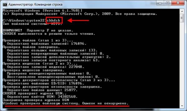
Когда я загружаю код, последовательный монитор печатает:
В моем PZEM L и N подключены к напряжению, и он его не измеряет. Почему?

Вы проверили, имеет ли PZEM правильный адрес на шине? Согласно репозиторию , конструктор, который вы использовали, получает необязательный параметр addr , который по умолчанию равен 0xF8 . Кроме того, вы можете использовать isnan(. ) вместо == NAN проверки NaN .
Решил проблему. Контакты 10 и 11 поддерживают SoftwareSerial на Arduino Mega R3 2560, поэтому мне пришлось переместить их с контактов 18TX и 19RX.
Почему вы используете серийный номер программного обеспечения? Mega имеет 4 аппаратных последовательных порта.
Pzem 004t подключение к компьютеру


Compatibility
| MCU | Hardware Serial | Software Serial | Not Tested | Examples | Notes |
|---|---|---|---|---|---|
| ATmega168 | X | HardwareSerial SoftwareSerial | |||
| ATmega328 ( Arduino Uno ) | (:white_check_mark:) | :heavy_check_mark: | HardwareSerial SoftwareSerial | HW Serial conflicts with Debug output. It can be used however without having any Serial Console output | |
| ATmega2560 ( Arduino Mega ) | :heavy_check_mark: | :heavy_check_mark: | HardwareSerial SoftwareSerial | ||
| ESP8266 | (:white_check_mark:) | :heavy_check_mark: | SoftwareSerial | HW Serial conflicts with Debug output Serial | |
| ESP32 | :heavy_check_mark: | :x: | HardwareSerial | SW Serial not really needed as ESP32 has 3 HW serials with configurable pins | |
| STM32 BluePill | X |
This example uses Hardware Serial2 in order to interface with the PZEM module. Note that not all MCUs feature multiple Serial ports. It won’t for example work on the Arduino Uno .
Measuring home energy consumption with the PZEM004T and ESP8266
First of all a very BIG WARNING: This project works with AC mains current, which, where I live, is 220V AC, meaning that extra precautions must be taken, since risk of serious injuries and/or death is possible.
The PZEM004T
The Peacefair PZEM004T device (available at the usual far east shopping web sites) is a device that can measure energy consumption by monitoring a live AC mains wire using an inductor as the measuring sensor. Take notice there are currently at least (3/2020) two versions: V2.0 which uses the standard serial protocol, and V3.0 that uses Modbus. This project uses V2.0.
One of the wires that carries the current (normally the AC power phase) goes through the inductor so that the current that flows through it can be measured and hence the other measurements, including power consumption, can be also measured.
The PZEM004T can be bought with two types of inductor, one that opens up and can clip on the wire of interest, and the other type that requires to disconnect and connect the wire of interest, so that it passes through the inductor core. I’ve chosen the former, since in this case I do not need to do any disconnection/connections on the electric mains board, and so it is way safer and easier to add and remove the measurement device.

PZEM 004T
The PZEMM04T outputs the collected data through an opto-coupled isolated serial port that allows to retrieve values for voltage, current/intensity, current power consumption and energy accumulated consumption.
The device that connects to the PZEM serial port must provide power to it (5V), and so the serial port data lines are 5V level, which means that we should use a 5v to 3.3V level converter to connect to the ESP8266. While there are several hacks to make the PZEM004T serial port to use 3.3V on the serial port, and hence have 3.3V data lines, I just used a simple level converter to connect the serial port to the ESP8266, and avoid in this way any modifications to the PZEM-004T. The serial port connector is a 4 Pin JST-XH connector.
So the basic schematics for using the PZEM004T is as simple as the following highly professionally drawn schematic shows:
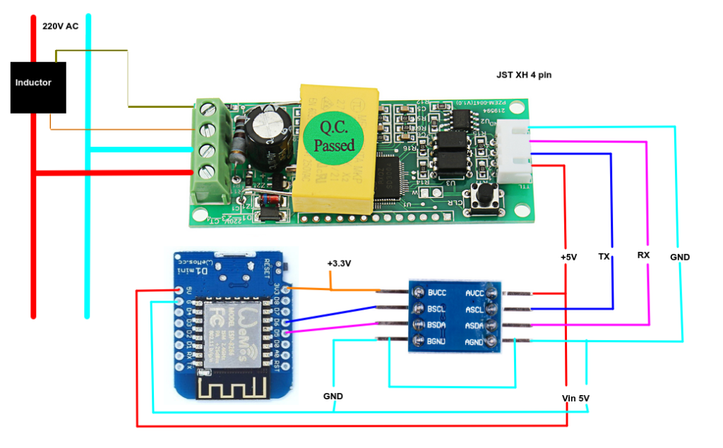
PZEM004T And Wemos D1 connection schematic
Two things of notice:
- The Ground connection – The serial port uses the same ground as the Wemos D1.
- The Power supply – Wemos D1 is powered through the 5V pin, NOT through the 3.3v pin, since we need 5V to power up the PZEM serial port.
The level converter is just a simple, cheap I2C level converter, used in this case to level convert the serial data lines.
Also the above schematic shows that the TX and RX pins connect to the Wemos D6 and D5 pins, since I’ll be using software serial, but the depicted connections are just an example, since the pins to be used can be software defined.
In my code I use the connections the other way around ( D5-TX, D6-RX) so beware to how the pins are connected and how they are defined at the software level.
Powering up the ESP8266 Wemos D1
I’ll be using the Wemos D1 ESP8266 based boards, as we can see on the above schematics (associated to a prototype shield to solder the connections and the level converter), we need to power it up using 5V. The ESP8266 uses 3.3v, but the Wemos board has a 5V input and a 5V to 3.3V converter, so no issues there. The PZEM004T on the other hand uses 220V, and since the ESP8266 will be near the PZEM004T, it makes sense to get the 5V CC from the 220V AC to power up the Wemos D1 board.
The 220V AC to 5V CC can be achieved in several ways, and since I’ll be installing all this in a DIN case on my home electricity mains board, the easiest solution is just to buy a 5V output 220V based DIN power supply for around 10/15€. This is the easiest and safest solution.
There are other solutions, including the one that I’m using that is based on the 5V HLK-PM01 based modules. This requires some assembly and also be aware that there are fake HLK modules around.
Do not connect the HLK-PM01 without the associated protection components, namely fuses, VDR, and the most important component the thermal fuse of 72ºC (Celsius!) that will cut off the power to anything after it (including the VDR) if the temperature of the HLK module or it’s surroundings rises above the 72ºC temperature. I’ve not soldered the thermal fuse, since the heat from the soldering iron can destroy it, just used a two terminal with screws to connect it.
The schematic used is the following one:
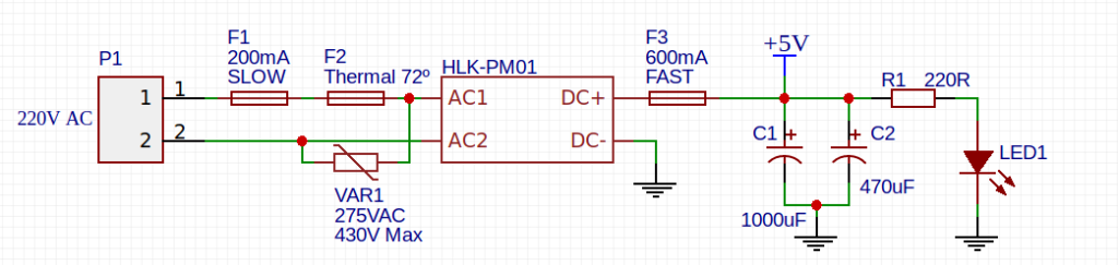
5V Power supply
The PZEM-004T, the HLK based power supply and the Wemos D1 ESP8266 module are inside a double length project DIN case so that all components can be safely installed on the mains electricity board.
Since all is self contained on the DIN case, all is needed is to clip the inductor on the main phase wire entering the mains board (and it is easy since the inductor is an open clip on type), and connect the components to the 220V AC power. I’ve derived the power from one of the circuit breakers that already protects a house circuit, which adds an additional layer of protection.